Bump Integrator
- home
- Civil Engineering
- Bitumin & Asphalt Testing Eqipment
- Bump Integrator
Bump Integrator
Short Discription :
A bump integrator (also known as a rough meter, shock integrator, or automatic road unevenness recorder) is a specialized device used in civil engineering and road maintenance to quantitatively measure the surface roughness or unevenness of pavements. It assesses how “bumpy” a road is by capturing vertical deflections caused by irregularities, providing a key indicator of ride quality, safety, and structural integrity. This tool is particularly valuable for unpaved roads, highways, and remote areas where advanced laser-based systems might be impractical due to cost or accessibility.
Standard Following :
IS 1209, IS 1448: Part 21, IS 1448: Part 66,ASTM D92, ISO 2592,ASTM D93,IP 36,AASHTO T48,ISO 2719, IP 34
Brochure:
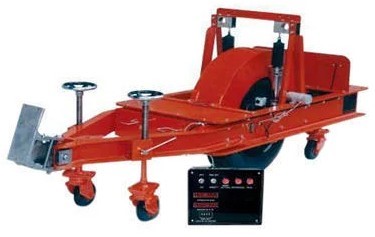
The bump integrator operates on the principle of dynamic response measurement, integrating (summing) vertical displacements over a distance traveled. Unlike static profilometers that scan surfaces without motion, it relies on the physical interaction between a vehicle’s axle and the road. Here’s a step-by-step breakdown:
- Mechanical Setup:
- The core component is a single-wheeled trailer (often called a “fifth-wheel” or axle-mounted unit) towed behind a vehicle, such as a jeep or survey truck.
- The wheel is connected to the trailer’s frame via a pivoting arm or linkage that allows free vertical movement. This arm is typically spring-loaded or uses pneumatic damping to mimic a vehicle’s suspension response.
- A pneumatic tire (e.g., with specific air pressure, often 30-40 psi) is used for consistent contact with the road surface. The tire’s deflection absorbs and transmits “bumps” (upward jolts) and “dips” (downward drops).
- Sensing Vertical Motion:
- As the vehicle moves at a constant speed (standard: 32 km/h or 20 mph to simulate typical traffic), the wheel encounters surface irregularities.
- These cause relative vertical displacements between the axle (wheel) and the chassis (frame). Upward bumps push the axle up relative to the frame; downward dips do the opposite.
- A mechanical or electronic linkage converts these bidirectional vertical oscillations into unidirectional rotations of a counting mechanism. This is often achieved via a rack-and-pinion system or a similar transducer:
- Upward motion rotates a gear in one direction.
- Downward motion is rectified (e.g., via a one-way clutch) to add to the same rotational tally, ensuring all irregularities contribute positively to the total “bump” count.
- Integration and Measurement:
- The rotations are “integrated” electronically: A counter (digital LCD or microprocessor-based) accumulates the total deflections.
- Distance is tracked via the wheel’s revolutions (e.g., using an odometer or encoder). A preset facility allows testing over fixed segments (e.g., 100m or 1km).
- Raw output: Cumulative counts (e.g., in arbitrary units). These are converted to the Unevenness Index (UI) in cm/km using a calibration formula: UI = B×C / N×D
- Where:
- B = Bump integrator reading (cumulative counts).
- C = Calibration constant (from lab tests on known rough surfaces).
- N = Number of wheel revolutions in the test section.
- D = Wheel circumference or distance per revolution.
- Modern variants integrate with GPS for real-time mapping and minimal operator input.
- Calibration and Standards:
- Before use, the device is calibrated on a reference surface with known IRI (e.g., via laser profilometer). This ensures accuracy within ±5-10%.
- Standards like IRC:SP 16-2004 (India) or ASTM E1926 classify it as a response-based meter, suitable for IRI calculations up to 10 m/km.
Component | Function | Typical Tech |
Wheel/Tire | Contacts road; transmits vertical forces | Pneumatic, 10-12″ diameter |
Linkage/Arm | Converts up/down motion to rotation | Rack-and-pinion or pendulum |
Counter/Display | Integrates and shows counts | Digital LCD or microprocessor |
Distance Tracker | Measures path length | Wheel encoder or odometer |
Trailer Frame | Mounts to towing vehicle | Lightweight steel/aluminum |
How It Is Used In Practice
Survey Process:
- Mount the trailer to a vehicle (e.g., at the rear axle for stability).
- Drive along the wheel path (right or left lane) at 32 km/h, avoiding acceleration/braking.
- Record readings every 100-500m; reset counter as needed.
- Post-process data with software (e.g., ROMDAS) for IRI, GIS mapping, or video correlation.
- Output Interpretation:
- Unevenness Index (cm/km): <200 = Excellent; 200-380 = Good; 380-650 = Fair; >650 = Poor.
- Correlates to IRI (m/km): Roughly UI/100 ≈ IRI for moderate roughness.
- Factors affecting readings: Speed variance (±2 km/h tolerance), tire pressure, vehicle load.
- Integration with Modern Systems:
- Often paired with ROMDAS (Road Surface Management Systems) for automated data logging, event rating (e.g., potholes), and export to GIS tools.
- In remote surveys, it’s battery-powered and requires no internet, making it ideal for developing regions.
Nothing To Show
Nothing To Show